Poulan 416833 User Manual
Browse online or download User Manual for Cars Poulan 416833. Poulan 416833 User Manual
- Page / 32
- Table of contents
- TROUBLESHOOTING
- BOOKMARKS
Rated. / 5. Based on customer reviews
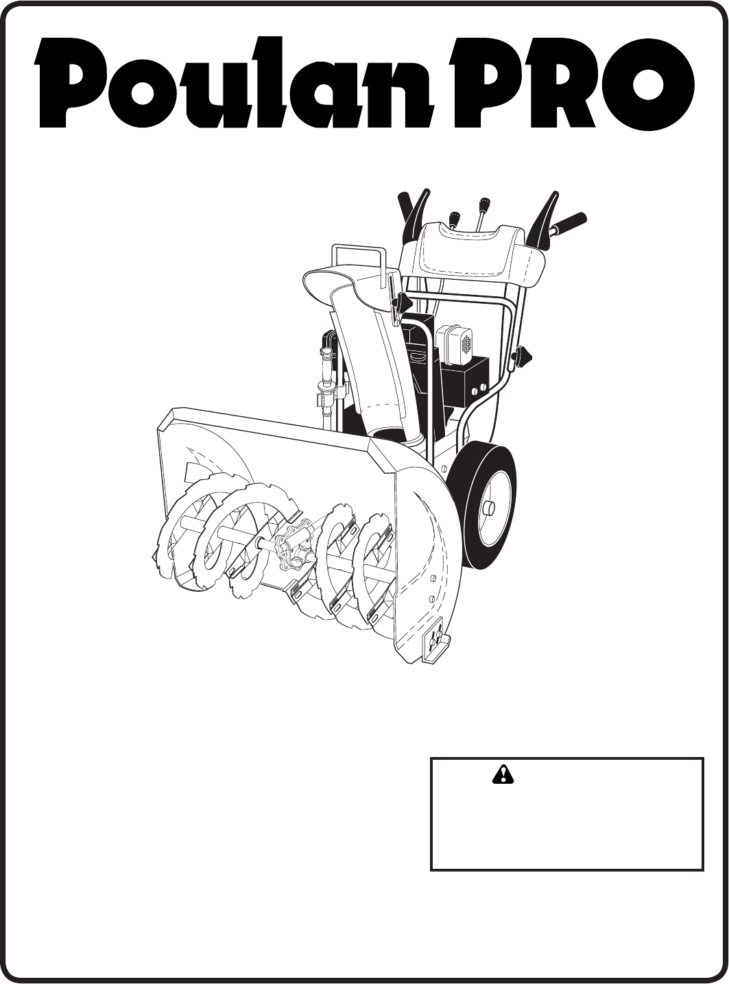
OWNER'S MANUAL
MODEL NUMBER:
PP10530ES
SNOW THROWER
Always Wear Eye Protection During Operation
IMPORTANT MANUAL Do Not Throw Away
WARNING:
Read the Owner's Manual and
fol low all Warnings and Safety
In struc tions. Fail ure to do so
can result in serious injury.
416833 09.12.07 TH
Printed in the U.S.A.
Summary of Contents
Page 1 - PP10530ES
OWNER'S MANUALMODEL NUMBER:PP10530ESSNOW THROWER Always Wear Eye Protection During OperationIMPORTANT MANUAL Do Not Throw Away WARNING:Read the
Page 2 - IMPORTANT
10OPERATIONTO THROW SNOW (See Fig. 14)The auger rotation is controlled by the auger control lever located on the right side handle.• Squeeze auger co
Page 3 - TABLE OF CONTENTS
11TO ADJUST SKID PLATES (See Fig. 17)NOTE: The wrench provided in your parts bag may be used to adjust the skid plates.Skid plates are located on each
Page 4 - ASSEMBLY / PRE-OPERATION
12OPERATIONCOLD START - ELECTRIC STARTER1. Insert safety ignition key (packed separately in parts bag) into ignition slot until it clicks. DO NOT tu
Page 5
13GENERAL REC OM MEN DA TIONSThe warranty on this snow thrower does not cover items that have been sub ject ed to operator abuse or negligence. To re
Page 6
14MAINTENANCEAUGER GEAR CASE• The gear case was filled with lubricant to the proper level at the factory. The only time the lubricant needs attention
Page 7
15CAUTION: Do not substitute. Use only original equip ment capscrew/shear bolts as sup plied with your snow thrower.4. Connect spark plug wire to spa
Page 8
16BELT KEEPERIDLER ARM SQUARE HOLEBOLTTRACTION DRIVE BELTCLUTCHING IDLER ARM BRACKETAUGER BELTFLAT WASHERAUGER PULLEYAUGERHOUSINGFRAMEENGINEPULLEYLOCK
Page 9
17SERVICE AND ADJUSTMENTSSTORAGEImmediately prepare your unit for storage at the end of the season or if the unit will not be used for 30 days or more
Page 10 - OPERATION
18Does not start 1. Fuel shut-off valve (if so 1. Turn fuel shut-off valve to OPEN position. equipped) in OFF position. 2. Safety ignition
Page 11
19SERVICE NOTES
Page 12
2IMPORTANTSafe Operation Practices for Walk-Behind Snow ThrowersThis snow thrower is capable of amputating hands and feet and throwing objects.Failure
Page 13 - MAINTENANCE
20REPAIR PARTS SNOW THROWER - MODEL PP10530ES (96192001802)AUGER HOUSING / IMPELLER ASSEMBLY6659912778611571013414161536375047424244272743434638454
Page 14
21KEY PART NO. NO. DESCRIPTION 4 191079 Pulley, Impeller 5 188909 Bearing Assembly, Flange 6 155377 Nut, Hex Flange 5/16-18 7 1803
Page 15 - SERVICE AND ADJUSTMENTS
22REPAIR PARTS SNOW THROWER - MODEL PP10530ES (96192001802)CONTROL PANEL / DISCHARGE CHUTE321261922262827272520297456881618171014313159111222232223
Page 16
23REPAIR PARTS SNOW THROWER - MODEL PP10530ES (96192001802)CONTROL PANEL / DISCHARGE CHUTEKEY PART NO. NO. DESCRIPTION 1 414280 Knob, Leve
Page 17
24REPAIR PARTS SNOW THROWER - MODEL PP10530ES (96192001802)HANDLES343742101523222727221532313230313839763625551828289181926242425554029121115111115
Page 18 - TROUBLESHOOTING
25KEY PART NO. NO. DESCRIPTION 1 402682x479 Lever, Auger Control, RH 2 412681x479 Lever, Traction Drive Control LH 5 169675 Retainer,
Page 19 - SERVICE NOTES
26REPAIR PARTS SNOW THROWER - MODEL PP10530ES (96192001802)DRIVE44444224311112255522204121171336141918181524363534373191223262925443328322744
Page 20 - 07 AIG plug_r1
27REPAIR PARTS SNOW THROWER - MODEL PP10530ES (96192001802)DRIVENOTE: All component dimensions given in U.S. inches. 1 inch = 25.4 mmIMPORTANT
Page 21 - KEY PART
28REPAIR PARTS SNOW THROWER - MODEL PP10530ES (96192001802)CHASSIS / ENGINE / PULLEYS61917102122232346428912131527262524187201454046444950515235343
Page 22
29REPAIR PARTS SNOW THROWER - MODEL PP10530ES (96192001802)CHASSIS / ENGINE / PULLEYSNOTE: All component dimensions given in U.S. inches. 1 in
Page 23
3CONGRATULATIONS on your purchase of a new snow thrower. It has been designed, engineered and man u fac -tured to give best possible dependability an
Page 24
30REPAIR PARTS SNOW THROWER - MODEL PP10530ES (96192001802)WHEELS / DECALS7323032301518171913201127271916201111111114151213181412443134342832133222
Page 25
31KEY PART NO. NO. DESCRIPTION 1 192092X421 Wheel Assembly, 16", Power Steering, LH 2 155443 Pin, Klik 1/4 3 405161 Cover, Pow
Page 26
LIMITED WARRANTYThe Manufacturer warrants to the original consumer purchaser that this product as manufactured is free from defects in materials and w
Page 27
4PARTS PACKED SEPARATELY IN CARTONASSEMBLY / PRE-OPERATIONRead these instructions and this manual in its entirety before you attempt to assemble or op
Page 28 - CHASSIS / ENGINE / PULLEYS
5ASSEMBLY / PRE-OPERATIONNOTE: The multi-wrench may be used for assembly of the chute rotator head to snow thrower and making ad just ments to the ski
Page 29
6ASSEMBLY / PRE-OPERATIONINSTALL DISCHARGE CHUTE / CHUTE ROTATOR HEAD (See Fig. 7)NOTE: The multi-wrench provided in your parts bag may be used to ins
Page 30 - WHEELS / DECALS
7OPERATIONKNOW YOUR SNOW THROWERREAD THIS OWNER'S MANUAL AND ALL SAFETY RULES BEFORE OPERATING YOUR SNOW THROWER. Compare the illustrations with
Page 31
8OPERATIONThrottle/engine control - used to se lect either FAST or SLOW engine speed and to STOP the engine.Traction drive control lever - used to eng
Page 32 - LIMITED WARRANTY
9The operation of any snow thrower can result in foreign objects thrown into the eyes, which can result in severe eye damage. Always wear safety glas
Related products and manuals for Cars Poulan 416833
Cars Poulan 96192003200 User Manual
 (40 pages)
(40 pages)
Cars Poulan 415332 User Manual
(36 pages)
(36 pages)
Cars Poulan 421469 User Manual
(40 pages)
(40 pages)
Cars Poulan 437738 User Manual
(44 pages)
(44 pages)
Cars Poulan 414949 User Manual
 (52 pages)
(52 pages)
Cars Poulan 199375 User Manual
(20 pages)
(20 pages)
Cars Poulan 437685 User Manual
(44 pages)
(44 pages)
Cars Poulan 422073 User Manual
(40 pages)
(40 pages)
Cars Poulan 96194000504 User Manual
(56 pages)
(56 pages)
Cars Poulan 96194000801 User Manual
(38 pages)
(38 pages)
Cars Poulan 435557 User Manual
(44 pages)
(44 pages)
Cars Poulan 96194000601 User Manual
(52 pages)
(52 pages)
Cars Poulan 961980025 User Manual
(40 pages)
(40 pages)
Cars Poulan 403919 User Manual
(20 pages)
(20 pages)
Cars Poulan 961980020 User Manual
(32 pages)
(32 pages)
Cars Poulan 416829 User Manual
(32 pages)
(32 pages)
Cars Poulan 96194000500 User Manual
(48 pages)
(48 pages)
Cars Poulan 96192004301 User Manual
(44 pages)
(44 pages)
Cars Poulan 418962 User Manual
(32 pages)
(32 pages)
Cars Poulan 422075 User Manual
(40 pages)
(40 pages)
© 2020, manymanuals.com. All rights reserved. | 0.695 s |
 Manymanuals.com
 Manymanuals.de
 Manymanuals.fr
 Manymanuals.it
 Manymanuals.pl
 Manymanuals.cz
 Manymanuals.es
 Manymanuals-pt.com
Comments to this Manuals